Friday, May 30, 2014

How to model a Fiat Car 500 with Sketchup

Simone Piccioni

This post has little tutorial because they lack many passages difficult to explain when the model is complex to implement and especially because everyone has their own technique, but may give you some ideas.

First I tried a good image in the network blueprint, after uploading it to Sketchup and designed the contours of the body, I started to model starting from the front wheel arches. Personally I like a lot of eye shape and helped with some photos found on the net.

After finishing the bodywork I used the plugin "Subdivide and Smooth" and to round it to check for any inaccuracy.

How to model a Fiat Car 500 with Sketchup  

At this point I began to shape the bonnet then I created all around a rim bent inwards to give it thickness , in this way, when it is placed on the body , the effect is better.

How to model a Fiat Car 500 with Sketchup 

It 's time the bonnet and the parts that compose it.
 
 How to model a Fiat Car 500 with Sketchup 

Missing doors that I modeled roughly on the inside.

How to model a Fiat Car 500 with Sketchup 

They could not miss the glass with their seals,

How to model a Fiat Car 500 with Sketchup  

and the bumper with headlights and the Fiat logo in the center.

How to model a Fiat Car 500 with Sketchup   

This is the floor with the wheels and the rear seat. Even in this case, the rear seat is quite approximate because that is what you should see less then it is useless to burden the model.

How to model a Fiat Car 500 with Sketchup   

But this car without seats and steering wheel does not go anywhere!

How to model a Fiat Car 500 with Sketchup   

So taking a cue from other photos found on the net I started modeling the steering wheel, odometer and instrument panel complete with ashtrays and buttons.

Even in this case, to round off, I used the plugin "Subdivide and smooth".

How to model a Fiat Car 500 with Sketchup 

How to model a Fiat Car 500 with Sketchup  

I put together all the pieces and ...

How to model a Fiat Car 500 with Sketchup 

How to model a Fiat Car 500 with Sketchup 

my Fiat 500 ... it's over!

How to model a Fiat Car 500 with Sketchup 

~~~~~~~~~~~~~~~~~~~~~
Published By
Arka Roy
www.sketchup-ur-space.com
~~~~~~~~~~~~~~~~~~~~~


Thursday, May 29, 2014

Designing video surveillance systems using 3D visualization

Göran Sandberg, Axis Communications

Security is often an integral part of the design process of new buildings - and an important consideration especially in large buildings such as airport terminals, or office complexes. Video surveillance cameras are used to monitor key areas such as entrances or high security zones, but it is important to understand where exactly to place them and what technical specifications are required to achieve optimal coverage.

Installation of the surveillance systems also needs to meet the expectation of the end users. What can be seen and how will the different scenes look like when viewed through the eyes of a camera are some the basic questions to ask in order to help clients understand both the capabilities and limitations of different features, or systems in general. A well-functioning system that does not meet customers’ expectation is not going to inspire clients’ confidence in future projects.

Deciding on the number, type and position of video surveillance cameras needed has traditionally required complex and time-consuming manual calculations. 3D visualization now makes the system designers' lives much easier and helps them do their job more cost-efficiently and accurately: New tools are available that integrates with popular CAD software and assist designers with the planning and layout of complete video surveillance systems.

Axis Communications, a leader in network video, is one company that offers a range of free tools that integrate with Autodesk Revit, SketchUp and Microsoft Visio - some of the most popular design software solutions that are widely used in architectural planning, building layout and system design. Available for download from the Internet as an addition to the CAD software, and with camera models available for import into CAD drawings; tools like these help designers decide on the ideal position for each camera by simulating camera coverage based on the camera's field of view and required resolution.
  
Designing video surveillance systems using 3D visualization 
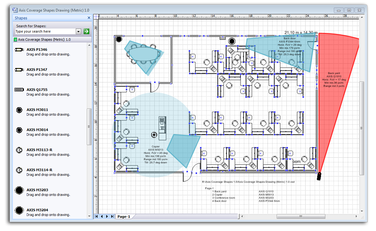
Axis Coverage Shapes for Microsoft Visio helps security system designers decide on the ideal position for each camera by simulating camera coverage based on camera field of view and required resolution.

How it works

Designers can import existing drawings and building layouts or uses the software to draw up the layout of the area they need covered by video surveillance, and then use a simple drag-and-drop function to choose and place cameras directly into the building drawing plans. Realistic, interactive 3D camera models in Autodesk Revit and SketchUp illustrate what the camera set-up will look like in real life, how the cameras integrate with their surroundings, and which area the video surveillance system will cover once installed. Users can choose from a large range of cameras and mounts and place them on any surface in the building plan. Once placed in the design, the software shows the camera's entire field of view as a colored area, with a resolution guide that helps determine the area where the target image solution is met.

To achieve the best coverage with the video surveillance system and optimize the system layout, the software allows designers to try out and compare different camera models, mounting positions and view angles. The software includes controls so users can specify values such as the required focal length, target resolution and mounting height. Users can interactively move the cameras by dragging them to different mounting points and pan or tilt them to determine the camera's field of view for various setups.

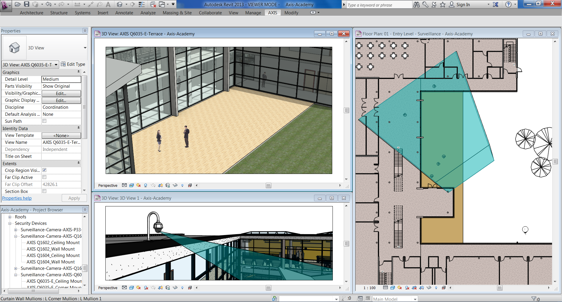
 One feature uniquely available for Autodesk Revit and SketchUp is a camera view feature that lets users switch to 3D views as seen from the security camera's point of view, and look through the lens of the camera literally at the click of a button. In SketchUp, this view, the camera can also be rotated or its angle adjusted and the user can see how this changes the field of view from the camera. This allows designers to get a good impression of what the final video surveillance scene will look like at an early stage in the design project, and identify any objects that might obstruct the camera's field of view such as columns or walls.

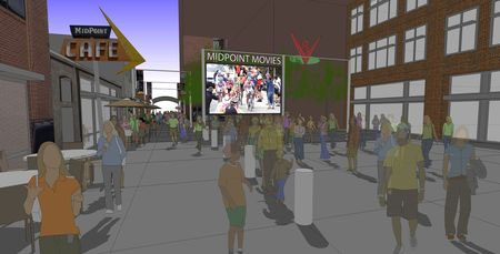
Once all cameras have been placed in the building design, it is then easy to verify the coverage area for the entire video surveillance solution. These images/scenes can also be used talking to the end user in regards to the systems’ functionality, and help out setting the correct expectations which can then be achieved by the system once installed.

Designing video surveillance systems using 3D visualization  

Axis Camera Families for Autodesk Revit offers detailed metadata required for Building Information Modeling (BIM) and allows security system designers to interactively visualize camera coverage.

SketchUp vs Autodesk Revit

SketchUp is a popular and readily accessible 3D CAD software that is particularly easy to use, while Autodesk Revit offers some more advanced and powerful design features that are useful especially in larger design and building projects. To make full use of those, the camera models for Autodesk Revit include detailed metadata required for Building Information Modeling (BIM), a process involving the generation and management of digital representations of physical and functional characteristics of places. They are files which can be exchanged or networked to support decision-making about a place. From inside the CAD drawing, users can access information about each camera such as the model number, focal range, resolution, mounting options and mounting accessories available, as well as power consumption. Once the design is complete, a camera summary lists all cameras used in the design, including any mounting accessories required for the installation.

There are a number of benefits in using 3D visualization tools when designing video surveillance systems.

The most obvious benefit is how 3D visualization helps with camera selection and placement. With these tools, system designers have easy access to a complete range of different cameras directly inside the software, including links to relevant technical specifications. By dragging and dropping the cameras in the CAD design and moving them around, they can see what each camera looks like in its environment from a design perspective, and view the camera's coverage for all the different camera types and possible mounting points. This allows them to decide which camera is best suited for the scene that needs to be monitored, and where it should be positioned.

3D visualization tools also help system designers to determine and meet the operational requirements for each video surveillance camera, such as ensuring that the camera has enough resolution, expressed in pixels per foot or per meter to identify a person entering a building through a particular doorway, or to be able to apply intelligent video analytics. With an image resolution guide, the tools provide clear guidance on the image quality that can be expected from each camera in the given setup, and they clearly show the area in the camera's field of view where the required target resolution will be achieved. By exploring using different cameras and mounting options for the video surveillance solution, system designers can make sure that the finished and installed system will not only cover the right areas in or outside the building, but also deliver the required image quality.

Designing video surveillance systems using 3D visualization  

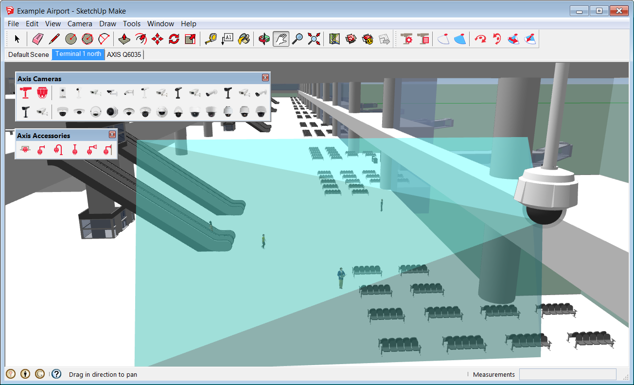
With Axis Camera Extension for SketchUp, security system designers can evaluate how cameras fit into the building layout and easily spot if the camera view coverage is obstructed by columns or walls.

Autodesk Revit and SketchUp both include advanced features that let users simulate the movement of the sun throughout the year, and Autodesk Revit can even simulate foliage growth on nearby trees and shrubs. Both are important in understanding the light conditions in which each camera will operate. For example, in winter the sun might be so low that it shines into a camera's lens through a window, or foliage might be so dense in summer that an area in the building becomes very dark or the view from a camera might become obstructed. In both cases, simulating and visualizing the setup will help the system designer decide whether a camera needs to be moved, or a different camera chosen that can cope with difficult light conditions.

Finally, 3D visualization tools are a useful aid for system designers in setting the right expectations with their clients. By demonstrating exactly what the installed system will look like, what it will cover and what camera views to expect, clients will be able to understand the capabilities and limits of the system. The installation and approval process can be streamlined and the list of issues that will need to be fixed before a project can be signed off can be significantly reduced.

Summary

To achieve the best level of security and avoid blind spots that could potentially become a security issue, security systems need to be planned at the same time as other essential services such as electrics and plumbing. With an integrated video surveillance system planning tool, designers can see exactly how the cameras fit into the building layout and can easily detect if views are obstructed by columns or walls, or if the camera installation conflicts with any other building systems such as mechanical, electrical and plumbing installations. This helps to manage customers’ expectations when potential issues can be identified and tackled as early as possible.

With interactive 3D visualization tools like these, architects, engineers and system designers can improve planning and work more efficiently. The result is more effective value engineering, device placement, conflict identification and aesthetic coordination.

~~~~~~~~~~~~~~~~~~~~~
Published By
Arka Roy
www.sketchup-ur-space.com
~~~~~~~~~~~~~~~~~~~~~ 

Wednesday, May 28, 2014

LightWave 11.6 and NevronMotion Final Releases Now Available

The LightWave 3D Group, a division of NewTek, Inc., has made available the final release of LightWave 11.6 software for 3D modeling, animation, and rendering. In addition, the company announced today the final release of the NevronMotion plug-in for LightWave 11.6, which uses the Microsoft Kinect camera to capture motion in real time for retargeting to 3D or live-performance characters.

NevronMotion also simplifies retargeting data from standard motion capture files directly into the LightWave interface.

LightWave 11.6 introduces new features for modeling, animating, capturing, retargeting, and inputting and outputting to 3D.

Animate in New Ways: With the Spline Control tool, nulls or other objects act as nodes in a spline to control or deform objects such as tentacles, tails, whips or even elevators; Raycast Motion utilizes raycasting technology to make an animated object aware of its surroundings;, and the Compound Node feature can simplify complex networks down to a single node.

Streamline Real-Time Virtual Production, Pre-Viz, and Game Development: Use NVIDIA CgFX shader technology to create 3D assets for virtual production, pre-visualization, or game development and view assets within LightWave OpenGL exactly as they will appear in the final real-time display engine. Users can also place Normal Maps on 3D objects to make lower-polygon objects or characters display as higher-resolution objects, and create custom CgFX shaders or use existing CgFX shaders.

Output to 3D Printers: LightWave Modeler now includes new import and export options to support the popular STL and PLY file formats. VRML is also supported and offers surface color data for 3D color printing of objects with texture maps. Also included is full control of the export format used, whether in ASCII or binary, the up direction, and units for export. New geometry clean up tools specifically for 3D printing output are also included.

Review in Full Stereoscopic 3D: With support for NVIDIA 3D Vision, 3D Vision Pro, and HDMI stereo devices, artists and designers can visualize high-quality advanced stereoscopic 3D environments across multiple devices, including enabled desktop monitors and multi-projector wall displays.

LightWave 11.6 and NevronMotion Final Releases Now Available   

TheNevronMotion plug-in for LightWave 11.6 extends the software's Virtual Studio Tools to:
  • Capture live-rig motion with the Microsoft Kinect camera
  • Retarget motion capture directly in LightWave Layout
  • Save and adjust captured motion data from the Kinect camera
  • Easily adjust arm and leg mocap positions and layer hand-keyed animation on top of motion capture files
  • Save and load retargeting presets for FBX, BVH, or custom setups
  • Preset rigs for Kinect and motion capture formats
  • Quickly bake out motion to character rigs
LightWave 11.6 is priced at $1,495 and the NevronMotion plug-in is priced at $299. Registered LightWave 11 customers can upgrade to LightWave 11.6 free of charge; upgrade pricing from LightWave 10 or earlier versions is $695. Educational pricing is also available.

~~~~~~~~~~~~~~~~~~~~~
Published By
Arka Roy
www.sketchup-ur-space.com
~~~~~~~~~~~~~~~~~~~~~

Tuesday, May 27, 2014

Place Making with a SketchUp Model

Place Making with a SketchUp Model 

I recently created a blog post about visualizing a repurposed alley in Boulder, Colorado using quickly generated hand drawings. That effort evolved into a more detailed exploration of the alley improvements in the format of a presentation SketchUp model.

This colllection of images show how I constructed the SketchUp model which revealed a series of alternative alley uses, shadow studies and eye-level views. I learned from this exercise that there are design projects that may not require any drawings to communicate their basic concepts and that a well crafted SketchUp model may be more than adequate to convey your big idea.

Place Making with a SketchUp Model  

Repurposed Alleys. Many downtown service alleys are being converted to commercial uses such as restaurants, concert venues and special events. These photos are from two alleys in San Francisco that were transformed into outdoor dining spaces during certain hours of the day and then converted back to their original service use all other times. These were the inspiration for how I approached building the SketchUp model (below).

Place Making with a SketchUp Model 

Base SketchUp Model I call this type of SketchUp model a “stage set model” for it is constructed with no more than a series of empty shapes with photographic facades applies to each face. I photographed all of the existing buildings and applied them to specific faces of the model. The resulting 3D SketchUp model was accurate enough to convey the existing neighborhood condition and spaces between buildings. The base image (streets and sidewalks) was saved from Google Earth.

Place Making with a SketchUp Model  

Strategic Model Views. You can see from these two views that there is a large open space in the central portion of the alley. I developed several different design scenarios using that space as an outdoor food court with food trucks (shown) or as an art fair with tents, or even as an outdoor movie theater.

Each alternative was saved on a different layer in the model. I then established a series of more than 10 model scenes (views) that showed the alley from above and at eye level. Those views were very helpful for studying and documenting how the sun cast shadows at different times of the day and season. 

Place Making with a SketchUp Model 

Alley Entrance Signage. This view angle of the Lawry Lane alley entrance was established as if I were observing from a second floor window across the street. The building facades are from digital photographs I took during a site visit. I constructed the sign, furniture and populated the model with a mix of 2D and 3D people, plants and other elements to establish the character of the alley space.

Place Making with a SketchUp Model  

Alley SketchUp Entourage. Look carefully at the many different elements that have been placed into the basic alley model. I added 3D sign letters to the building facade, decorative “buttons” on the glass storefront, 3D and 2D people, custom umbrellas with red banding, and regularly spaced poles with banners. I added the red colored stripe on the banners to coordinate with the umbrellas and inserted images of bicycle racers that I photographed at a local competition. I fabricated the Grants Cafe sign from an image I downloaded from the internet and made into a SketchUp component.

Place Making with a SketchUp Model 

Place Making with a SketchUp Model  

Central Food Court. I created a scene with several food trucks (downloaded from SketchUp 3D Warehouse) surrounding an outdoor seating area with shade umbrellas. This important urban space adjacent to the alley was developed with three different design options: food court, arts festival and outdoor movie theater. I exported jpegs of the three options from these two overhead and eye-level views.

Place Making with a SketchUp Model   

Strategically Placed Shade. This scene included a small pocket park adjacent to the alley planted with shade tress. I positioned the sun angle in such a way to cast tree shadows across the alley surface. Those shadows in combination with the umbrella shadows enhanced the setting. If I had more time to invest in the model detail, I would have added some elements to the table surfaces and seating in the pocket park. Flower pots and additional landscaping in the park would have also been worth adding to the model.

Place Making with a SketchUp Model  

Night Movie Scene. This outdoor movie theater scene wasn’t easy to create alone in SketchUp. I established the basic view and then added the bike race photograph and a dark gray overlay in Adobe Photoshop. Given more time, I could have created a more successful night time effect using other graphic alternatives. I don’t think this scene was very convincing - especially when you see hard shadows beneath each individual!

If you have a design project that has a high level of complexity and the need to be represented with multiple alternatives and views, consider building a semi-detailed SketchUp model and export different views for your presentation. One last note: all of my model views were exported at a high resolution 4000 pixels wide and saved as jpegs. Each had a consistent horizontal format and dimension.

~~~~~~~~~~~~~~~~~~~~~
Published By
Arka Roy
www.sketchup-ur-space.com
~~~~~~~~~~~~~~~~~~~~~